The City of Cumming
Cumming, Georgia is located in Forsyth County north of Atlanta, near Lake Sidney Lanier. Census estimates conducted in 2005 show the population of the city at around 6,000 people, however, the population of Forsyth County is estimated at over 100,000 people and growing. The City of Cumming supplies both the city and surrounding Forsyth County with processed potable water from Lake Lanier. Currently the City of Cumming and Forsyth County are permitted to withdraw a combined 34 million gallons of lake water per day for their potable water processing facilities (PWPF). To maintain a steady supply of water capable of quenching the ever-growing north Georgia area, Civil Engineering Consultants, Inc. of Marietta, Georgia designed a new raw water intake for the City at the inlet of Young Deer Creek to Lake Lanier, near the location of the City’s two existing intake structures.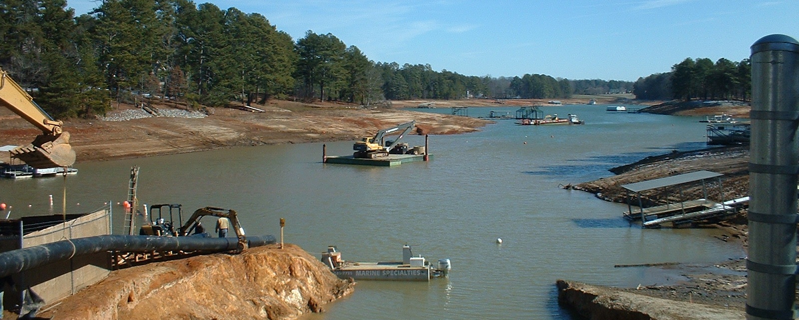
Project Overview
In April 2007, GeoSystems was contracted by the City of Cumming to provide a subsurface investigation for the new redundant raw water intake from Lake Lanier. The primary purpose of the study was to determine subsurface conditions at the site and provide geotechnical recommendations relative to the required deep excavation for the new wet well and trenchless underground construction of the intake pipe.The initial raw water intake design included a 45-foot inside diameter wet well and a 335-foot long, 66-inch diameter steel pipe intake. Planned wet well construction consisted of reinforced concrete with an indicated 3-foot thick foundation slab-on-grade. The bottom of the structure was planned at elevation 1025, with the foundation slab bearing near elevation 1022. A pump house was included on top of the wet well with a finished floor elevation of 1086. The steel intake pipe extended to the east from the wet well into the lake at an invert elevation of 1028 feet.
As construction of the wet well began, the state of Georgia and much of the southeast entered into prolonged historic drought conditions. The level of Lake Lanier dropped steadily and in December of 2007 the surface was measured at nearly 20 feet below the full pool elevation of 1070 feet mean-sea-level (msl). To maintain an adequate supply of water during the drought, the City undertook interim emergency measures; extending an existing withdrawal pipe and dredging around existing intake structures. To assure a long-term uninterrupted supply of water, the new redundant raw water intake plans were altered to include a deeper wet well and an approximate 3,100-foot extension of the withdrawal pipe further into the lake. The revised design lowered the wet well bottom to elevation 1017 feet and the 66-inch diameter intake pipe invert to elevation 1022 feet. The intake pipe extension consisted of installation of a 78-inch diameter steel pipe installed in an open trench dredged to an invert elevation of 1020 feet. The dredging extended southeasterly into the lake generally along the centerline of Young Deer Creek inlet to about 5000 feet northwest of Young Deer Park. Lake bottom elevations along the alignment ranged approximately from 1045 feet at the upper end to about 1020 feet in the deeper part of the lake near the end of the extension. GeoSystems completed additional studies in February 2008 to address planned trenching and dredging conditions along the 3,100-foot long pipe extension.
Key Words & Phrases
- Subsurface investigation
- Soil test borings
- Barge drilling
- Intake structure
- Lake Sydney Lanier
Investigation Procedures
Nine standard soil test borings and one auger boring were drilled to initially investigate the planned wet well structure and withdrawal pipe alignment. Six of the borings were drilled on the hillside above the shoreline, in the area of the wet well and along the intake pipe alignment. The four remaining borings were drilled along the pipe alignment within the lake. The test borings along the intake pipe alignment within the lake were completed using a drilling rig carried on a floating barge. The barge was located by triangulating from previous surveyed points along the shore line and held in place at each boring location by multiple heavy anchors. In addition to the borings, rock coring; installation of temporary piezometers; field permeability (slug) tests in the temporary piezometers; and laboratory soil classification, hydraulic conductivity, and triaxial shear strength analyses were performed.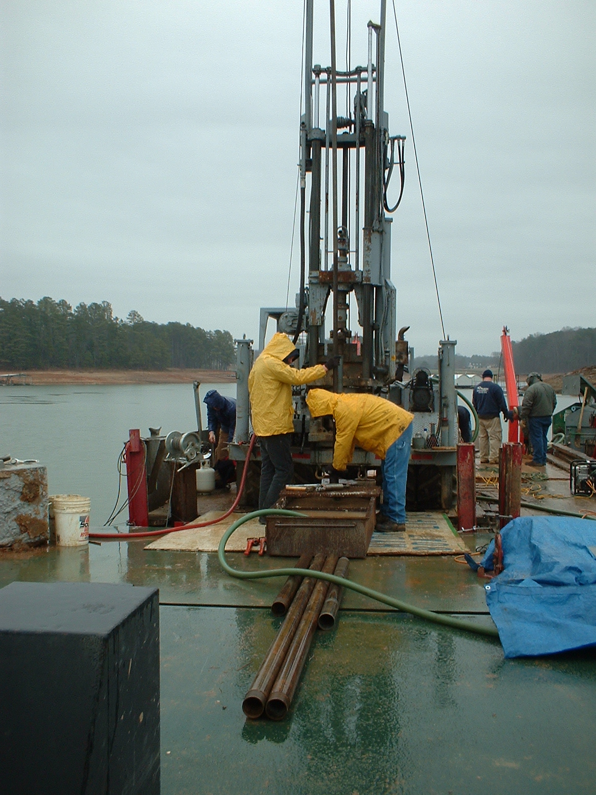
Investigation of the long intake pipe extension included eight additional soil test borings, also performed from the lake surface by a drill rig floating on a barge. Drilling conditions along the extension were not as calm as those in the sheltered inlet; however, multiple heavy anchors and installed drill casing proved sufficient to maintain the position of the barge for drilling at each boring. The borehole locations were established by aligning the barge and measuring distances between buoys previously placed by survey at known stations along the planned pipe alignment.
Analysis and Data Reduction
Conditions in the area of the wet well were found to be similar to previous investigations for the existing intake structures. Subsurface materials consisted mainly of deeply weathered residual soils generally underlying topsoil (on land) or lake sediment. Partially weathered rock was encountered in two borings and auger refusal material in one other boring. Excavation of some deep weathered rock and/or rock was indicated in the area of the wet well. Conventional jacking and bore or micro-tunneling were both determined to be feasible options for installation of the initial stretch of intake pipe.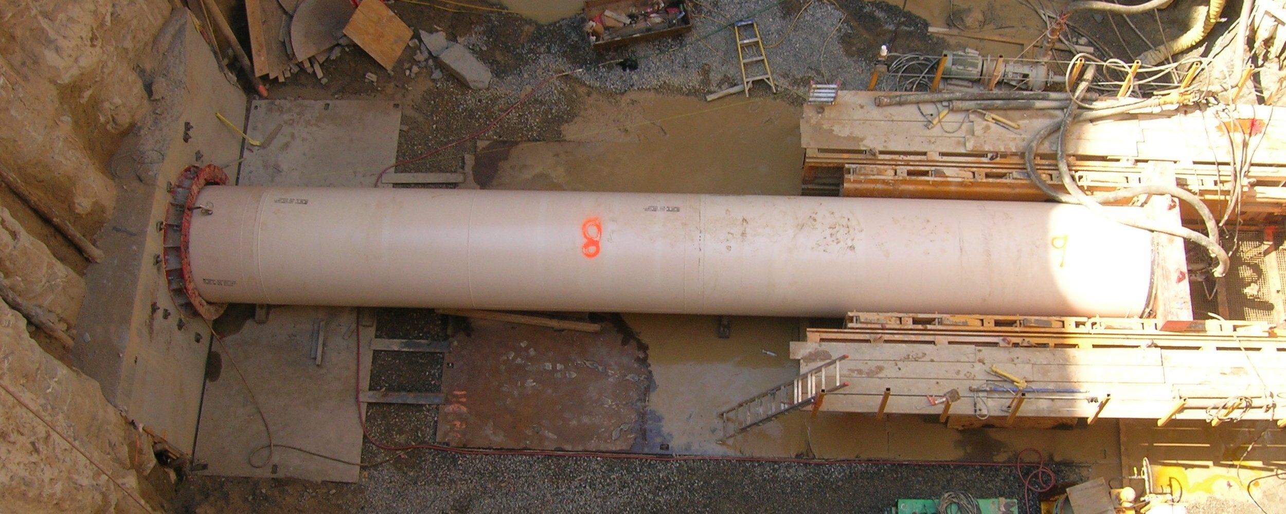
The majority of material encountered along the withdrawal pipe extension was described mainly as loose lake sediment and residual soils, with some partially weathered rock and refusal material encountered at two locations above the bottom of the trench. In one boring, about 3 feet of weathered rock was found above the planned invert elevation of 1020 feet. At another location weathered rock and auger refusal material (apparent rock) was encountered about 8 feet above the planned invert. GeoSystems predicted that mechanical dredging operations to remove the lake sediment and soft residual soils could be accomplished using either long-reach backhoe or clamshell excavators. Removal of partially weathered rock and/or rock would require difficult excavation techniques using a large backhoe equipped with sharp teeth buckets and/or blasting.
Conclusion
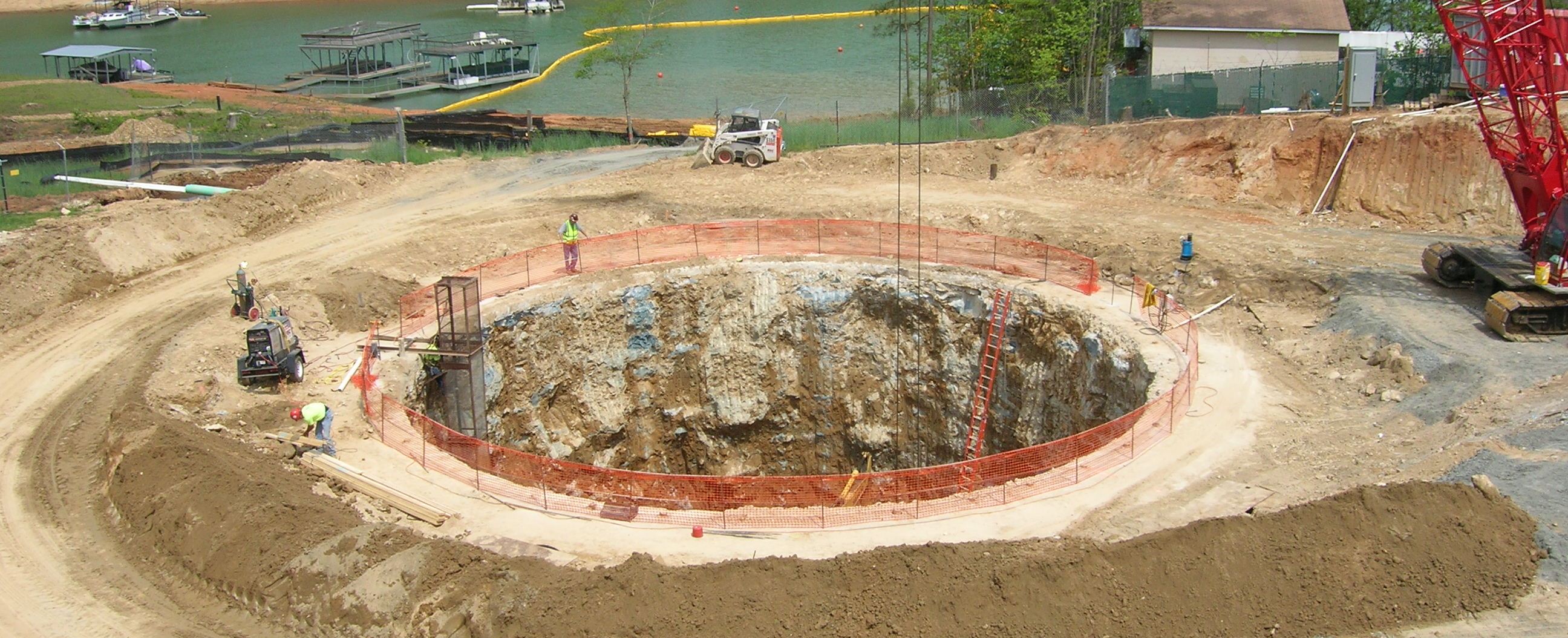
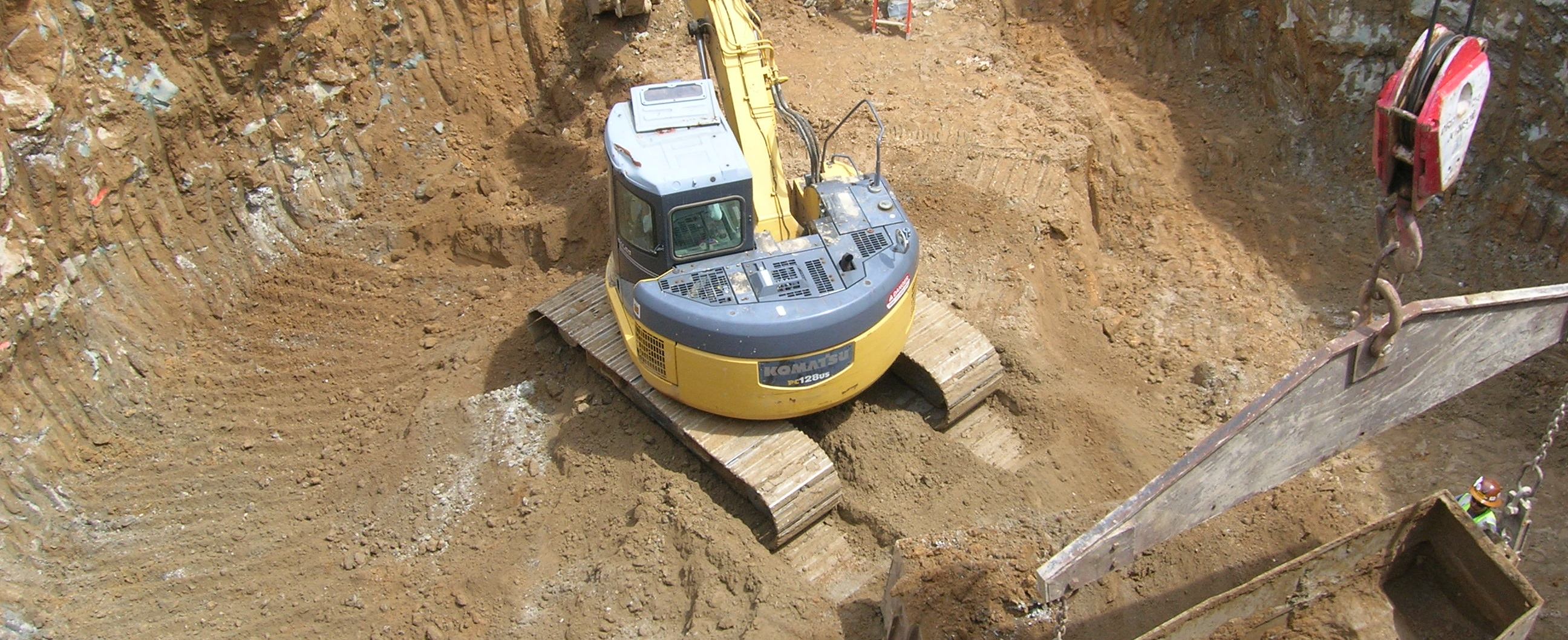
W.L. Haley & Company, Inc. was awarded the contract to construct the wet well and for installation of the intake piping. Hayward Baker, Inc. provided temporary shoring for support of the approximate 62-foot diameter wet well excavation. The excavation shoring system consisted of overlapping jet grout columns supplemented with micro-piles, intermediate of the grout columns, along the inside face of the excavation. Two rows of jet grout columns were installed on 5-foot centers along the excavation perimeter. The system also included nine, 100-foot deep, wells for dewatering on the exterior of the excavation. The initial 66-inch diameter, 335-foot long intake pipe was installed by microtunneling.GeoSystems provided observation of the excavation conditions and the wet well bearing materials during construction of the wet well and the intake pipe dredging operations. Conditions encountered were generally as described by GeoSystems’ previous geotechnical reports. Dredging for the extended intake pipe encountered some deep material that was difficult to extract with a cable operated clamshell bucket. Additional soil test borings performed by the contractor found limited areas of partially weathered rock materials above the trench invert elevation, as anticipated by GeoSystems. Various alternative excavation methods, including a long-reach track hoe and spudding to loosen the materials, were used to successfully complete the required dredging operations.
For more information about this and other projects please contact GeoSystems Engineering, Inc. at (678) 722-0340.
Spotlight Project
| PROJECT: | Raw Water Intake |
| LOCATION: | Cumming, Georgia |
| CLIENT: | City of Cumming |
| START DATE: | |
| END DATE: | |
| PROJECT COST: | |
| GEOSYSTEM COST: | |
| PDF: | City_of_Cumming_RWI.pdf |